企业MPLS VPN组网实操配置案例
全球互联网时代,简单的互联网已无法保证企业各种业务(如ERP系统、视频语音会议)的可靠传输,而传统的数字电路、以太专线却费用高昂。MPLS VPN企业组网方案正是为了满足跨国企业跨地域企业应用的高性价比方案。其具有更高的性价比、带宽可灵活调整、支持二层网络协议穿透(如 CDP,VLAN)、可针对业务性质的不同划分 CoS(Class of Service)、提供业界领先的服务水平承诺(SLA)等特点。
正因为MPLS VPN企业VPN组网方案已被广泛应用,在此小编为大家提供MPLS VPN组网案例资料,和大家分享一个MPLS VPN组网实操配置案例,具体组网需求如下:
1.各路由器基本信息配置
2.OSPF规范配置,修改网络类型为点对点
3.所有路由器运行OSPF,RT4 E3/0、RT5 E3/0 network至OSPF中,RT1E3/0重发布直连到OSPF中
4.所有路由器运行MPLS,标签分发协议为LDP
5.RT4和RT5运行IBGP,并将E3/1发布至BGP中
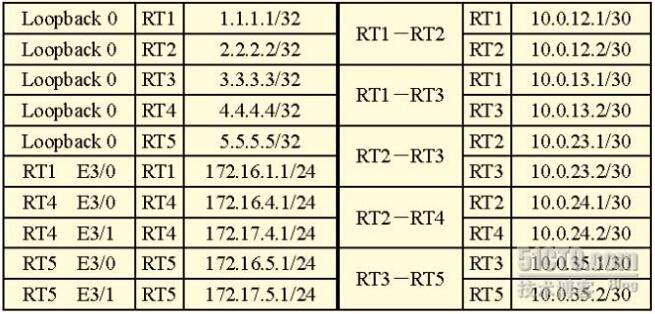
IP地址分配如下:
前面配置略
IGP配置如下:
RT1:
router ospf 1
router-id 1.1.1.1
passive-interface default
no passive-interface Serial0/1
no passive-interface Serial0/2
redistribute connected metric 1000 subnets
network 1.1.1.1 0.0.0.0 area 0
network 10.0.12.0 0.0.0.3 area 0
network 10.0.13.0 0.0.0.3 area 0
RT2:
router ospf 1
router-id 2.2.2.2
passive-interface default
no passive-interface Serial0/0
no passive-interface Serial0/1
no passive-interface FastEthernet1/0
network 2.2.2.2 0.0.0.0 area 0
network 10.0.12.0 0.0.0.3 area 0
network 10.0.23.0 0.0.0.3 area 0
network 10.0.24.0 0.0.0.3 area 0
interface f1/0
ip ospf network point-to-point
RT3:
router ospf 1
router-id 3.3.3.3
passive-interface default
no passive-interface Serial0/0
no passive-interface Serial0/1
no passive-interface FastEthernet1/0
network 3.3.3.3 0.0.0.0 area 0
network 10.0.13.0 0.0.0.3 area 0
network 10.0.23.0 0.0.0.3 area 0
network 10.0.35.0 0.0.0.3 area 0
interface f1/0
ip ospf network point-to-point
RT4:
router ospf 1
router-id 4.4.4.4
passive-interface default
no passive-interface Serial0/0
network 4.4.4.4 0.0.0.0 area 0
network 10.0.24.0 0.0.0.3 area 0
network 172.16.4.0 0.0.0.255 area 0
RT5:
router ospf 1
router-id 5.5.5.5
passive-interface default
no passive-interface Serial0/0
network 5.5.5.5 0.0.0.0 area 0
network 10.0.35.0 0.0.0.3 area 0
network 172.16.5.0 0.0.0.255 area 0
MPLS配置:
RT1、RT2、RT3、RT4、RT5如下配置:
全局配置模式:
ip cef //运行MPLS必须开启CEF
mpls ip //开启MPLS
mpls label protocol ldp //选择MPLS标签分发协议为LDP(默认是TDP,CISCO私有)
再在所有MPLS网络中的接口开启MPLS
RT1:
int s0/1
mpls ip
int s0/2
mpls ip
RT2的S0/0、F1/0、S0/1,RT3的S0/0、F1/0、S0/1,RT4、RT5的S0/1做以上配置
IBGP的配置:
RT4:
router bgp 65000
no synchronization
network 172.17.4.0 mask 255.255.255.0
neighbor 5.5.5.5 remote-as 65000
neighbor 5.5.5.5 update-source Loopback0
neighbor 5.5.5.5 next-hop-self
no auto-summary
RT5:
router bgp 65000
no synchronization
network 172.17.5.0 mask 255.255.255.0
neighbor 4.4.4.4 remote-as 65000
neighbor 4.4.4.4 update-source Loopback0
neighbor 4.4.4.4 next-hop-self
no auto-summary
LDP邻居建立过程请看http://tangfangxiao.blog.51cto.com/2116646/659741
RT1#show ip cef detail //查看CEF的详细信息
4.4.4.4/32, version 23, epoch 0, cached adjacency to Serial0/1
0 packets, 0 bytes
tag information set
local tag: 23 //本地标签18 也就是进来的标签,交换标签(SWAP)
fast tag rewrite with Se0/1, point2point, tags imposed: {22}//压入标签PUSH
22
via 10.0.12.2, Serial0/1, 0 dependencies
next hop 10.0.12.2, Serial0/1
valid cached adjacency
tag rewrite with Se0/1, point2point, tags imposed: {22}
RT1#show mpls ldp discovery //查看LDP发现消息
Local LDP Identifier:
1.1.1.1:0 //本地LDP标识为1.1.1.1
Discovery Sources:
Interfaces: //LDP发现消息的来源
Serial0/1 (ldp): xmit/recv //从S0/1接口发送或接收到LDP发现消息
LDP Id: 2.2.2.2:0 //LDP ID为2.2.2.2
Serial0/2 (ldp): xmit/recv//从S0/2接口发送或接收到LDP发现消息
LDP Id: 3.3.3.3:0 //LDP ID为3.3.3.3
RT1#show mpls ldp neighbor //查看LDP的邻居信息
Peer LDP Ident: 3.3.3.3:0; Local LDP Ident 1.1.1.1:0 //对端LDP
ID3.3.3.3和本地LDP ID 1.1.1.1
TCP connection: 3.3.3.3.37601 - 1.1.1.1.646 //TCP连接 IP+端口号
State: Oper; Msgs sent/rcvd: 30/31; Downstream //状态:运行中
Up time: 00:14:16
LDP discovery sources:
Serial0/2, Src IP addr: 10.0.13.2 //LDP发现消息的来源和IP
Addresses bound to peer LDP Ident: //对端LDP需要弹出MPLS标签的地址
10.0.13.2 3.3.3.3 10.0.23.2 10.0.35.1
Peer LDP Ident: 2.2.2.2:0; Local LDP Ident 1.1.1.1:0
TCP connection: 2.2.2.2.54420 - 1.1.1.1.646
State: Oper; Msgs sent/rcvd: 20/20; Downstream
Up time: 00:04:34
LDP discovery sources:
Serial0/1, Src IP addr: 10.0.12.2
Addresses bound to peer LDP Ident:
10.0.12.2 2.2.2.2 10.0.23.1 10.0.24.1
注意:MPLS的标签分发是随机的(从16往上递增,0-15为公认系统标签),你们有可能分得的标签跟我不一样!
我们来分析一下RT4的172.16.4.0这条路由在MPLS网络的传播:
首先RT4上运行了MPLS,会为所有的IGP路由表分发标签(BGP路由不发标签),RT2收到RT4分发的标签
RT2#show mpls ldp bindings //显示标签信息库
tib entry: 172.16.4.0/24, rev 18 //路由条目
local binding: tag: 20 //本地分发标签是20(发给所有LDP邻居)
remote binding: tsr: 4.4.4.4:0, tag:
imp-null //4.4.4.4分发的特殊标签3(用来作倒数第二跳弹出)
remote binding: tsr: 3.3.3.3:0, tag: 20 //3.3.3.3分发的标签20
remote binding: tsr: 1.1.1.1:0, tag: 24 //1.1.1.1分发的标签是24
RT2#show mpls forwarding-table //查看MPLS的转发表
Local Outgoing Prefix Bytes tag Outgoing Next Hop
tag tag or VC or Tunnel Id switched interface
20 Pop tag 172.16.4.0/24 0 Se0/1 point2point
本地标签20 出标签3 网络前缀 0表示是IPV4 出接口 下一跳(点对点)
RT2#show ip route
O 172.16.4.0 [110/110] via 10.0.24.2, 00:09:31, Serial0/1
从上面可以看出,MPLS路由器收到同条路由的多个标签,会进行优先,主要是根据IGP路由表中的下一跳来进行选择,如上MPLS选择的下一跳是跟IGP路由表是一样的
RT3#show mpls ldp bindings
tib entry: 172.16.4.0/24, rev 18
local binding: tag: 20 //本地分发标签是20(发给所有LDP邻居)
remote binding: tsr: 5.5.5.5:0, tag: 23
remote binding: tsr: 2.2.2.2:0, tag: 20 //从RT2上可以看出它为这条路由分发的标签是20
remote binding: tsr: 1.1.1.1:0, tag: 24
RT3#show mpls forwarding-table //查看MPLS的转发表
Local Outgoing Prefix Bytes tag Outgoing Next Hop
tag tag or VC or Tunnel Id switched interface
20 20 172.16.4.0/24 0 Fa1/0 10.0.23.1
172.16.4.0进标签是20(本地标签)出标签是20,下一跳为10.0.23.1,下一跳为F1/0
RT3#show ip route
O 172.16.4.0 [110/210] via 10.0.23.1, 00:11:23, FastEthernet1/0
可以看出MPLS选择优先选一跳是根据IGP路由表来的,如果IGP路由表中没有此路由,将不会进入MPLS转发表中
RT5:
RT5#show mpls ldp bindings
tib entry: 172.16.4.0/24, rev 24
local binding: tag: 23
remote binding: tsr: 3.3.3.3:0, tag: 20 //收到RT3发来的标签
RT5:show mpls forwarding-table
Local Outgoing Prefix Bytes tag Outgoing Next Hop
tag tag or VC or Tunnel Id switched interface
23 20 172.16.4.0/24 0 Se0/0 point2point
RT5#show ip route
O 172.16.4.0 [110/310] via 10.0.35.1, 02:00:34, Serial0/0
与上面类似,这里不再叙述!
MPLS是不会为BGP路由分发标签的,同时收到的路由如果在IGP中没有,也是不会进行MPLS的转发表的!
如RT5中有两条BGP路由,一条是自己产生的,另一条是学习到的:
RT5(config-if)#do show ip bgp
Network Next Hop Metric LocPrf Weight Path
*>i172.17.4.0/24 4.4.4.4 0 100 0 i
*> 172.17.5.0/24 0.0.0.0 0 32768 i
我们在RT4上查看标签信息库
RT3#show mpls ldp bindings
tib entry: 172.17.5.0/24, rev 34
remote binding: tsr: 5.5.5.5:0, tag: imp-null
//我们可以看到RT5为这条路由分发了一个标签3(这里会分发标签是因为是直连路由,)在这里并没有看到为172.17.4.0/24分发标签,因为它是BGP路由,MPLS不为BGP路由分发标签
RT3#show mpls forwarding-table
Local Outgoing Prefix Bytes tag Outgoing Next Hop
tag tag or VC or Tunnel Id switched interface
16 Pop tag 1.1.1.1/32 0 Se0/0 point2point
17 Pop tag 2.2.2.2/32 0 Fa1/0 10.0.23.1
18 Pop tag 10.0.12.0/30 0 Fa1/0 10.0.23.1
Pop tag 10.0.12.0/30 0 Se0/0 point2point
19 Pop tag 10.0.24.0/30 0 Fa1/0 10.0.23.1
20 22 4.4.4.4/32 30679 Fa1/0 10.0.23.1
21 Pop tag 5.5.5.5/32 5459 Se0/1 point2point
22 23 172.16.4.0/24 31211 Fa1/0 10.0.23.1
23 Pop tag 172.16.5.0/24 0 Se0/1 point2point
我们在RT3的MPLS转发中并没有看到172.17.5.0/24网段,因为在RT3中的路由表中没有,所以不会进入MPLS的转发表中!
我们来分析一下RT5的172.16.5.1与172.16.4.1的通信过程:
首先RT5查询MPLS的转发表,找到对应路由出标签号为20(下以所涉及的转发表可以看上面),所以再数据包的IP头部前面加入4个字节的MPLS标签,标签号为20,EXP位为0,栈底位为1,同时将IP中的TTL复制到MPLS标签中(这里始发为255),再封装成HDLC的帧发送,RT3从S0/1接口收到后,去掉二层帧头,查看MPLS标签入标签号为20,查找MPLS转发表出标签号为20,出接口为F1/0,同时交换MPLS标签号为20,EXP位为0,栈底位为1,同时TTL-1(转发一次MPLS TTL-1但是IP中的TTL是不变的,它只涉及到二层),再封装成以太网帧发送,RT2从F1/0接收到数据,拆二层封装,查MPLS入标签号为20再查找MPLS转发表,出标签为
Pop tag
(特殊标签3倒数第二跳弹出)删除MPLS标签同时将MPLS标签中的TTL复制到IP报文的TTL中,然后查找IP全局路由表,TTL-1=253封装成以太网帧,再转发给下一跳,RT4收到数据直接转发给相应接口,然后再向RT5发送回应数据包,以上过程的逆过程!
补充:在做倒数第二跳弹出时,E-LSR可能会分发的几种标签
标签3 隐式空标签 (上游LSR不添加标签,弹出最外层MPLS标签)
标签0 IPV4显示空标签 (上游LSR会添加标签0,E-LSR收到后,直接弹出标签进行IVP4转发)
标签2 IPV6显示空标签(上游LSR会添加标签0,E-LSR收到后,直接弹出标签进行IVP6转发)
关于MPLS中的MTU问题:
问题1:
RT5#ping 172.16.4.1 source 172.16.5.1 size 1500 df-bit
Type escape sequence to abort.
Sending 5, 1500-byte ICMP Echos to 172.16.4.1, timeout is 2 seconds:
Packet sent with a source address of 172.16.5.1
Packet sent with the DF bit set
.....
Success rate is 0 percent (0/5)
这里我PING满包1500不分片不能通,再测试,
RT5#ping 172.16.4.1 source 172.16.5.1 size 1496 df-bit
Type escape sequence to abort.
Sending 5, 1496-byte ICMP Echos to 172.16.4.1, timeout is 2 seconds:
Packet sent with a source address of 172.16.5.1
Packet sent with the DF bit set
!!!!!
Success rate is 100 percent (5/5), round-trip min/avg/max = 40/88/132
ms
RT5#ping 172.16.4.1 source 172.16.5.1 size 1497 df-bit
PING包1496不分片却能通
Type escape sequence to abort.
Sending 5, 1497-byte ICMP Echos to 172.16.4.1, timeout is 2 seconds:
Packet sent with a source address of 172.16.5.1
Packet sent with the DF bit set
.....
Success rate is 0 percent (0/5)
PING包1497不分片却不能通
分析:IP报文在MPLS链路上转发时,由于压入了MPLS标签,故报文长度增加了,原来的1500字节变成了1504(1497+4=1501)都超过了MPLS的默认MTU1500字节,所以不通,然而1496+4=1500不分片刚好通过,所以能通!
问题2:
修改链路上所有接口的MPLS MTU为1600
R5S0/0、RT3S0/1、F1/0、RT2S0/1、F1/0、R4S0/0都做修改配置如下:
int s0/0
mpls mtu 1600
其它类似
RT5#ping 172.16.4.1 source 172.16.5.1 size 1500 df-bit
Type escape sequence to abort.
Sending 5, 1500-byte ICMP Echos to 172.16.4.1, timeout is 2 seconds:
Packet sent with a source address of 172.16.5.1
Packet sent with the DF bit set
!!!!!
Success rate is 100 percent (5/5), round-trip min/avg/max = 64/104/164
ms
现在能PING了!
RT5#ping 172.16.4.1 source 172.16.5.1 size 1501 df-bit
Type escape sequence to abort.
Sending 5, 1501-byte ICMP Echos to 172.16.4.1, timeout is 2 seconds:
Packet sent with a source address of 172.16.5.1
Packet sent with the DF bit set
M.M.M
Success rate is 0 percent (0/5)
如果我PING包1501不分片为什么不能通!
分析:照理说1501+4=1505要小于1600啊,应该能通啊!我开始就范了这样的错误,大家注意下这里还有个接口MTU默认是1500字节,也就是在不分片的情况下网络层的包大小为1500字节,1501不分片大于1500,所以它再封装成二层的时候会提示包过大,导致封装失败!如果是1500它刚好能封装,然后再加MPLS标签大于了1500,这里已经跟这个接口MTU没什么关系了,它只管三层的,再多加几个MPLS标签都没关系,只要MPLS MTU大于或等于它就行!
问题3:
如果我不改这条链路上所有接口的MPLS MTU,只修改R5S0/0、RT3S0/1、RT2S0/1、R4S0/0
的接口MTU为1600,修改RT3的F1/0、RT2F1/0的MPLS MTU为1600,ping包500不分片能通吗?
配置如下:
RT4、RT5配置如下:
int s0/0
mtu 1600
RT2、RT3配置如下:
int s0/1
mtu 1600
int f1/0
mpls mtu 1600
RT5#ping 172.16.4.1 source 172.16.5.1 size 1500 df-bit
Type escape sequence to abort.
Sending 5, 1500-byte ICMP Echos to 172.16.4.1, timeout is 2 seconds:
Packet sent with a source address of 172.16.5.1
Packet sent with the DF bit set
!!!!!
Success rate is 100 percent (5/5), round-trip min/avg/max = 48/88/136
ms
显然也是能通的!原因是修改接口的MTU同时也就修改了MPLS MTU。因为我用模拟器做实验,也许是IOS过低不能修改以太网接口的MTU,所以就不能演示PNG超过1500不分片的包了.
RT2#show mpls int s0/1 detail //查看MPLS接口的详细信息
Interface Serial0/1:
IP labeling enabled (ldp):
Interface config
LSP Tunnel labeling not enabled
BGP tagging not enabled
Tagging operational
Fast Switching Vectors:
IP to MPLS Fast Switching Vector
MPLS Turbo Vector
MTU = 1600 //我只修改了接口的MTU
问题4:
RT5pingRT1的S0/2
Type escape sequence to abort.
Sending 5, 1500-byte ICMP Echos to 10.0.13.1, timeout is 2 seconds:
Packet sent with the DF bit set
!!!!!
Success rate is 100 percent (5/5), round-trip min/avg/max = 28/63/92 ms
如果你对MPLS VPN感兴趣,可以联系我们,我们会给你更好的建议。
下一篇:企业全球分部VPN网络互联方案